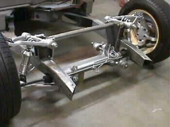
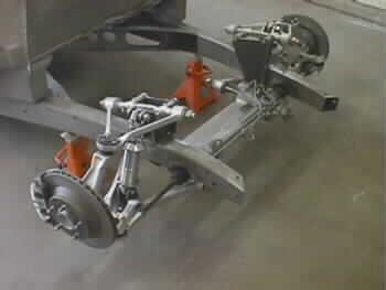
With the Front Axle Centerline marked in Step 1, Mark installed the C4 Corvette front suspension crossmember in the frame. Mark is using the 1988-96 Corvette front suspension with the 12″ brake rotors. The rack & pinion C-notches were also marked, cut and welded in.
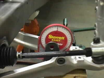
Next, the crossmember was slid up between the frame rails and centered left to right. Equal amounts can be trimmed of the crossmember to slide up between the frame rails, if needed. Measure front the lower control arm mounting tube to the frame on both side to insure it is centered. The Lower control arm tubes should be up 1 degree, front to rear, with the vehicle at ride height rake.
The lower front coil-over/Shockwave mounts were installed into the lower control arms. These are pushed as far towards the rear as possible. Next, the new urethane lower arm bushings were installed. Why do this, you say? We feel the the lower arms, with all of the load, should have 5/8″ bolts instead of the stock 12MM. We have custom bushings and bolts made to accommodate this. The front suspension is bolted into place and the lower control arms are leveled.
With the suspension all mounted into place and the vehicle mocked up at it’s ride height, Mark set the alignment listed in the instructions. Mark took the the coil-over and set it at it’s specified ride height. That’s the distance where it should be when the car is fully loaded and done. Mark then bolt the coil-overs to the lower mount and make a cardboard copy of the upper coil-over mount. He trimmed the template to where the coil-over fits. It should “butt” up against the upper arm mount as well as sit on the top of the frame. We always suggest to check to make sure that there is enough clearance for the coil-over or Shockwave when the suspension goes thru it total travel.
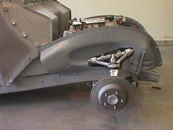
Mark made a template of the inner fender panels to determine how to do the cut-outs for the front suspension. This allowed Mark to do a nice neat job on the cut-outs.


